This is your very first post. Click the Edit link to modify or delete it, or start a new post. If you like, use this post to tell readers why you started this blog and what you plan to do with it.


This is your very first post. Click the Edit link to modify or delete it, or start a new post. If you like, use this post to tell readers why you started this blog and what you plan to do with it.


Time have fly so fast, as it fly away time by time the works have been hard for me. Facing all the consequences because we know the end is coming. We are dealing with subjects that it is really hard to analyze and also to learn. But at the end of the day we survived. Yes we can survive.
I’ve been dealing with physics since day 1, its been a year with this subject it makes my life miserable but surely it makes my life, real and be with reality. In our daily life we’ve dealing with physics and the only subject that it is true and be with us till our death.
let me count 1-10 in tagalog version, to enumerate the things that physics teach me.
Isa, Isang araw simula noong natutunan ko na ang physics ,it is real and the only subject that it is in reality. unang beses natutunan ko na may mga bagay pala na pwedeng i’apply sa totoong buhay, na kayang ipaliwanag lahat para matuto sa mga pagkakamali hindi gaya niya na nasa imahinasyon lang. Unang group activity and it is in titled ” treasure hunting” ang pinaka paborito ko sa lahat na tungkol sa VECTORS kung saan kailangan mong sunudin ang mapa para ituro kung nasan ang inaasam mong premyo kasi kahit doon lang maging masaya naman tayo. Unang premyo na nakuha ko simula noong nagstart ang klase ,na bunga ng pagod at tiyaga. Physics teach me how to be a patient person to follow rules because in order for us to survive we must follow the rules where in the price is waiting for us.
Dalawa, Dalawang beses kong sinubokang sumuko pero may pangarap ako sa buhay. Dalawang Taon na pagiging Senior High, sa pangalawang pagkakataon dito ako natuto na lahat ng bagay ay importante,na ang buhay ay parang nakakapit tayo sa isang rubberband na dapat hindi natin bitawan kasi paniguradong yung ibang nakakapit ay masasaktan gaya sa physics na group activity namin where in the toy was named a CATAPULT, the catapult will be needing a rubber band in order for it to stretch as it can so that it can throw the ball far enough. Once na nasira ang rubber band paniguradong talo tayo sa group activity natin na yun. Physics teach me that there will always be one thing that stay at your side, Physics will not leave you not like the one who leave you at first.
Tatlo, “I LOVE PHYSICS” tatlong salita na akala ko hindi ko sasabihin. Tatlong salita na hirap paniwalaan pero Oo simula noong napagtantuan ko na mahalaga pala ito, dito ako nag simula na makinig sa klase dahil may asignatura pa pala na nasa realidad. Physics are everywhere, as you pull and push the door the thing that is applying their is FORCE. And Love is the only force that is capable of transforming an enemy into a friend. Tatlong salita na importante sa atin ang FORCE, LOVE AND A FRIEND. Physics teach me that you can love the things you hate, well in order to love them it must undergo in a process.
Apat, Apat na taon bago ako naging Senior High School Student. Apat na taon at dagdagan mo pa ng Dalawa magtatapos na kami. Huling buwan na at dito na ang huling pahina pero nandyan pa rin si journal na nagsasabing “every step of your way i must be there” pero siguro ito na ang huli sa muli nating pagkikita our journal. In journal it teach me that “Time is gold” kapag may free time ka wag mo ng ipaumaga girl siguradong magrurush ka na naman.
Lima, Limang salita na nagpapalakas ng loob ko sa tuwing ako’y dehado, limang salita na alam ko na laging sumusuporta sa akin. Limang salita para sa mga estudyante na kagaya ko. Limang salita sa mga nahihirapan na sa physics, Limang salita rin para sa mga taong patuloy umaasa. Limang salita “LALABAN AKO HANGGA’T KAYA KO”
Anim, Pero sana hindi umabot sa anim na salita, anim na salita na kinakatakutan ko. Anim na salita na ayaw kong makita sa notification bar ko, Anim na salita na magpapaiyak sa akin. Anim na salita ” YOUR JOURNAL HAS BEEN GRADED, ZERO (0)”
Pito, Pitong Letra na nagbukas sa aking isipan na meron pa palang isang bagay na nasa realidad. Pitong Letra na napakahalaga sa ating buhay, pitong letra na pinag aaralan ang matter, energy, particles, waves, gravity at iba pa. Pitong letra na binigyan ako ng pagkakataon na maniwala na may mga bagay sa realidad. Pitong Letra “PHYSICS”
Walo, Ang pinakapaborito kong numero. Baligtarin mo at dun mo makikita ang infinity – something without any bound or larger than any natural number. Minsan binigyan kami ng isang gawain kung kaya ba namin itong gawin tungkol sa CONCAVE AND CONVEX LENS kung saan ang object ay ang given pwedeng nasa ” At C, Between C and F, At F and etc.” Physics teach me that there is no easy way, in order to find it easy you must undergo in a hard level to be a successful one.
Siyam, Pagdating ng Siyam alam ko ika’y pagod na. Siyam na beses akong nag isip kong itutuloy ko pa ba pero patapos na patapos na ang huling pahina ng SENIOR HIGH, patapos na ang mga ala ala natin na dapat huwag kalimutan, Siyam na buwan bago mag Marso alam ko lahat tayo ay pagod na pero kapit lang magwawakas na.
Sampu, At tuluyan ng maging Sampu dagdagan mo pa ng sampu yun ang bilang ng journal na nagawa ko ng sampung buwan. Sa Sampung buwan nagkakasama tayo mga alaala na meron tayo na pang habang buhay nating aalalahanin. Sir, Salamat sa Sampung Buwan at dagdagan mo pa ng Sampu dahil since Grade 11 ikaw yung nandyang para sa akin. Sir, Salamat at pinaintindi mo sa amin na ang Physics ay nasa realidad binigyan mo ako ng pagkakataon na may mga bagay pa pala na nasa realidad. Sampu at maraming beses ko mang ulit ulitin ang pasasalamat ko sa yo sir sa binahagi mong kaisipan sa amin. Oo mahirap ang physics pero kahit na mahirap at mahirap na intindihin nabigyan pa rin ako ng rason para mahalin ito. Sampung salita ang nasa isipan ko na gusto kong malaman mo sir, “MARAMING SALAMAT SA LAHAT SIR, PHYSICS TEACH ME SO WELL”.


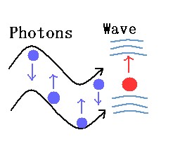
Light has a dual nature
1.Sometimes it behaves like a particle (called a photon), which explains how light travels in straight lines
2. Sometimes it behaves like a wave, which explains how light bends (or diffracts) around an object
3. Scientists accept the evidence that supports this dual nature of light (even though it intuitively doesn’t make sense to us!)
In Physics there are two fundamental “objects” of studying: waves and particles.
What is a wave?
A wave is a perturbation which propagates in time and space. You may think about an ocean wave, for instance. A wave can be divided, but cannot be localized with precision (you will understand why in this article). You can make a wave by just applying an oscillatory force to one end of a string (by shaking your hand, for example). 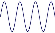
What is a particle?
One can say that it is something you can “touch”, can be localized and, by definition, it cannot be divided.

Newton thought that light was a particle because the edges of the shadows it created was extremely sharp and clear.
The theory of light being a particle completely vanished until the end of the 19th century when Albert Einstein revived it.
Einstein believed light is a particle (photon) . Scientists have combined both theory.
About the same time as Newton, Dutch physicist, Christian Huygens, believed that light was made up of waves vibrating up and down perpendicular to the direction of the light travels. It explained diffraction and could be demonstrated through experimentation.

The wave-like properties of light were demonstrated by the famous experiment first performed by Thomas Young in the early nineteenth century. In original experiment, a point source of light illuminates two narrow adjacent slits in a screen, and the image of the light that passes through the slits is observed on a second screen.
The dark and light regions are called interference fringes, the constructive and destructive interference of light waves.

However, notice that electrons do act as particles, as do photons. For example, they make a single strike on a cathode ray tube screen.

we do see the individual electrons (and photons) strike the screen, and with time the interference pattern builds up. Notice that with such a slow rate, each photon (or electron) is not interacting with other photons to produce the interference pattern. In fact, the photons are interacting with themselves, within their own wave packets to produce interference.

Two light rays pass through two slits, separated by a distance d and strike a screen a distance, L , from the slits

If d < < L then the difference in path length r1 – r2 travelled by the two rays is approximately:
r1 – r2  dsin
dsin 
where  is approximately equal to the angle that the rays make relative to a perpendicular line joining the slits to the screen.
If the rays were in phase when they passed through the slits, then the condition for constructive interference at the screen is:
dsin = m ,m =
,m =  1, 2,… whereas the condition for destructive interference at the screen is:
dsin = (m +  ) ,m = 1, 2,…
The points of constructive interference will appear as bright bands on the screen and the points of destructive interference will appear as dark bands. These dark and bright spots are called interference fringes.
Note:
sin y/L
so that the formulas specifying the y – coordinates of the bright and dark spots, respectively are:
y Bm =  brightspots
y Dm =  darkspots
The spacing between the dark spots is
 y =
y = 
If d < < L then the spacing between the interference can be large even when the wavelength of the light is very small (as in the case of visible light). This give a method for (indirectly) measuring the wavelength of light.
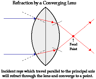
Any incident ray traveling parallel to the principal axis of a converging lens will refract through the lens and travel through the focal point on the opposite side of the lens.

It is the bending of a wave when it enters a medium where its speed is different called Refraction. The refraction of light when it passes from a fast medium to a slow medium bends the light ray toward the normal to the boundary between the two media.
This bending by refraction makes it possible for us to have lenses, magnifying glasses, prisms and rainbows. Even our eyes depend upon this bending of light. Without refraction, we wouldn’t be able to focus light onto our retina.
Light refracts whenever it travels at an angle into a substance with a different refractive index (optical density).
This change of direction is caused by a change in speed. For example, when light travels from air into water, it slows down, causing it to continue to travel at a different angle or direction.
How much does light bend?

When light travels from air into water, it slows down, causing it to change direction slightly. This change of direction is called refraction. When light enters a more dense substance (higher refractive index), it ‘bends’ more towards the normal line.
The amount of bending depends on two things:
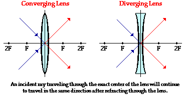
A lens is simply a curved block of glass or plastic. There are two kinds of lens.
A convex lens is thicker at the middle than it is at the edges. This is the kind of lens used for a magnifying glass. Parallel rays of light can be focused in to a focal point. A convex lens is called a converging lens.

Each light ray entering a converging (convex) lens refracts inwards as it enters the lens and inwards again as it leaves. These refractions cause parallel light rays to spread out, travelling directly away from an imaginary focal point.
Refraction Rules for a Converging Lens
 Method for Drawing Ray Diagrams
A concave lens curves is thinner at the middle than it is at the edges. Light rays refract outwards (spread apart) as they enter the lens and again as they leave. A concave lens is also called a diverging lens.

Each light ray entering a diverging (concave) lens refracts outwards as it enters the lens and outwards again as it leaves. These refractions cause parallel light rays to spread out, travelling directly away from an imaginary focal point.
Refraction Rules for a Diverging Lens

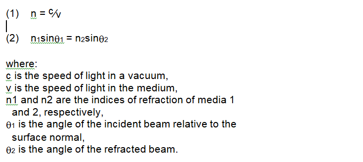
Where n1 is the refractive index of first medium and n2 is the refractive index of second medium, v1 is the speed of light in firs medium and v2 is the speed of light in second medium.

Reflection is when light bounces off an object. If the surface is smooth and shiny, like glass, water or polished metal, the light will reflect at the same angle as it hit the surface. This is called specular reflection.

Light rays are basically wave motions and they are capable of being reflected by an interface in between two mediums. Such interfaces are called Light Reflectors.
The most common Light reflector is the one we use many times a day, which is nothing but a plane mirror. But it is not only a plane mirror reflects light. Even a curved mirror does that though the nature of reflection of light by curved mirrors is different.

The law of reflection states that the angle of incidence is equal to the angle of reflection, or, stated mathematically.
The laws of reflection determine the reflection of incident light rays on reflecting surfaces, like mirrors, smooth metal surfaces, and clear water. Let’s consider a plane mirror as shown in the figure above. The law of reflection states that
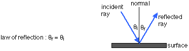
is the angle made by the ray incident on the surface from the line which is normal to the plane at the point of incidence.
is the angular reflection formed by a reflected ray and a perpendicular to the surface at the point of reflection.
F O R M U L A :
The Angle of incidence always equals the angle of reflection and the distance of image always equals the distance of object are called Angle of reflection formula.
if θi and θr are the angle of incidence and angle of reflection respectively, then
sin θi = sin θr
or
θi = θr
When light falls on a surface which is plane, the angle with which the light falls on the surface is equal to the angle with which the light reflects back and the incident ray, reflected ray and the normal ray lies in the same plane.
There are primarily two types of reflection.
Specular reflection – When light hits the smooth surface, reflected light rays travel in the same direction. For example, in case of mountains covered by lakes, we often see pictures of mountain appearing in lake. This is because lakes have smooth surface that reflects light in same direction and as such perfect image of the mountains is formed.

Diffused Reflection a reflective surface other than mirrors in general have a very rough finish. This may be due to wear and tear such as scratches and dents or dirt on the surface. Sometimes even the material of which the surface is made of matters. All this leads to a loss of both the brightness and the quality of the reflection. In case of such rough surfaces, the angle of reflection when compared between points is completely haphazard. For rough surfaces, the rays incident at slightly different points on the surface are reflected in completely different directions. This type of reflection is called diffused reflection, and is what enables us to see non-shiny objects.

Concave mirrors are used in certain types of astronomical telescopes called reflecting telescopes. The mirrors condense lots of light from faint sources in space onto a much smaller viewing area and allow the viewer to see far away objects and events in space that would be invisible to the naked eye.
When parallel light rays hit a concave mirror they reflect inwards towards a focal point (F). Each individual ray is still reflecting at the same angle as it hits that small part of the surface
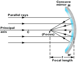

The following facts are used to construct ray diagrams:

Curved reflectors are used to make parallel rays of energy emerge from them.

Any ray that passes through the centre of curvature of the mirror will reflect back along its own path because the radius of a circle always hits the edge of the circle at 90 degrees – it hits it normally so the angle of incidence and reflection will both be zero.
To summary the Concave Mirror:
When parallel light rays hit a convex mirror they reflect outwards and travel directly away from an imaginary focal point (F). Each individual ray is still reflecting at the same angle as it hits that small part of the surface.
A Convex Mirror was described as a portion of a sphere that had been sliced away. If the outside of the sphere is silvered such that it can reflect light, then the mirror is said to be convex.

The center of that original sphere is known as the center of curvature (C) and the line that passes from the mirror’s surface through the sphere’s center is known as the principal axis. The mirror has a focal point (F) that is located along the principal axis, midway between the mirror’s surface and the center of curvature. Note that the center of curvature and the focal point are located on the side of the mirror opposite the object – behind the mirror. Since the focal point is located behind the convex mirror, such a mirror is said to have a negative focal length value.
A Convex Mirror is sometimes referred to as a diverging mirror due to the fact that incident light originating from the same point and will reflect off the mirror surface and diverge. The diagram at the right shows four incident rays originating from a point and incident towards a convex mirror.
 These four rays will each reflect according to the law of reflection. After reflection, the light rays diverge; subsequently they will never intersect on the object side of the mirror. For this reason, convex mirrors produce virtual images that are located somewhere behind the mirror.
An image is the location in space where it appears that light diverges from. Any observer from any position who is sighting along a line at the image location will view the object as a result of reflected light. Each observer sees the image in the same location regardless of the observer’s location. As the observer sights along a line, a ray of light is reflecting off the mirror to the observer’s eye.

Light rays originating at the object location are shown approaching and subsequently reflecting from the mirror surface. Each observer must sight along the line of a reflected ray to view the image of the object. Each ray is extended backwards to a point of intersection – this point of intersection of all extended reflected rays is the image location of the object.
On the image above it is a virtual image. Light does not actually pass through the image location. It only appears to observers as though all the reflected light from each part of the object is diverging from this virtual image location. The fact that all the reflected light from the object appears to diverge from this location in space means that any observer would view a replica or reproduction when sighting along a line at this location.
To summary the Convex Mirror:
Light is a transverse, electromagnetic wave that can be seen by humans. The wave nature of light was first illustrated through experiments on diffraction and interference. Like all electromagnetic waves, light can travel through a vacuum. The transverse nature of light can be demonstrated through polarization.
Light is produced by one of two methods
“In fact I have tried the experiment only at a short distance, less than a mile, from which I have not been able to ascertain with certainty whether the appearance of the opposite light was instantaneous or not; but if not instantaneous it is extraordinarily rapid” – Galileo Galilei, 1638
The speed of light in a vacuum is a universal constant in all reference frames.
In order to learn them our teacher gave us an activity where in you will draw the diagram of rays of : a. Concave Mirror b. Convex Mirror . Where in we don’t have the same places of object. The places of objects are ; Beyond C, At C, Between C and F, At F, and Between F and V (Vertex). At first we didn’t on how to draw the rays because we don’t have the same places of objects but in order to us to understand we helped each other problems. In some part we argue very much because somebody says that is the correct and some say it is wrong. So we gone through our notes where in our teacher discuss about on placing the rays. So at the end of it we learned on how to draw the rays eventhough we don’t have the samw places of objects. In every group activity we will always need your groupmates opinio in irder to learn from them the knowledge that they have.

When a current-carrying wire is placed in a magnetic field, it will experience the Lorentz Force. One of its example is a Electromagnetic Swing.
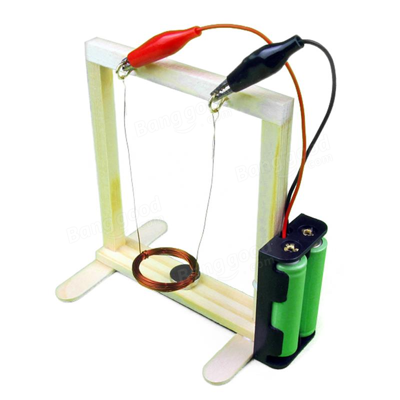 So this is our write up:
I. TITLE: Ready, Mag in Place, Charge, Swing!
II. OBJECTIVES:
III. MATERIALS:
IV. PROCEDURE:
V. OBSERVATIONS
Before we assembled the parts of the electromagnetic swing, we tried to do the activity. At first, we had a hard time to make it work and the swing is not that strong. We considered the length of the wire where in the shorter the wires, the stronger the swing. Also, we considered the distance of the wire to the magnet. If the wire is closer to the magnet, the swing is stronger. In addition, we noticed that the first swing is to the front. We have no pre- requisite knowledge regarding on the topic at hand so we decided to research on it.
VI. CONCEPTS
The Lorentz force is the combination of electric and magnetic force. It results from the interaction between the electromagnetic fields.
According to Maxwells equations of classical electrodynamics a changing electrical field leads to a magnetic field. Therefore a moving charge q surrounded by a magnetic field will experience a force F, called the Lorentz force:

Since we know current I is equals the charge per time

And the velocity is:

We get:

This looks more applicable to our setup. The following calculations are for sure just rough calculations. With the given setup it is not possible to make exact calculations. We just want to have a rough idea about the dimensions of the quantities we are dealing with. If you want to teach this kind of calculation to some students be sure to always have some error estimation afterwards.
So let’s see. Measuring the current carrying through the wire gives me:

The length of the copper wire is about:

Checking the datasheet of the magnet I’m using gives me:

So all together we get a Lorentz force of:

Therefore the resulting Lorentz force is perpendicular to the direction of the current AND the magnetic field lines. In order to find out about the direction of the Lorentz force we make use of the right-handed coordinates. Using thumb, index and middle finger will help us to figure out the direction of the Lorentz force.
Consider the following graphic to get an understanding of the “Three Finger Rule”:

If you are looking for the direction of the electrons flow, which is from minus to plus, you have to take the left hand. Therefore the left hand is used when talking about the technical current flow, which is from plus to minus.
This is the only thing you should be very cautious about. Since the meaning of the index and middle finger is always the same. So let’s put this straight:

· thumb = points in the direction of the velocity vector v
· index finger = points in the direction of the magnetic field vector B (from North to South)
· middle finger = points in the direction of the cross product F
VII. COMPUTATION
Given:
I= 0.5 A
l= 0.025 m
B= 1.5 T
F=?
F=I (l x B)
F=0.5 A (0.025 m x 1.5 T)
F=0.02 N
VIII. CONCLUSION
The electromagnetic swing shows the relationship between magnets and current carrying wire. There is a magnetic force created. The concept that governs this experiment is the Lorentz Force. We can also determine the direction of the current, magnetic force and field using either the right hand rule or the left hand rule where the thumb points the direction of the current, index finger points the direction of the magnetic field and the middle finger points the direction of the magnetic force. In addition, we have observed that there are external factors that can affect the magnetic force such as the length of the wire and its distance to the magnet.
IX. DOCUMENTATION
MATERIALS NEEDED TO CREATE A SWING:


Electromagnetism, the magnetism was produced by electricity. Today, electromagnetism is used in many electric devices. However, until electromagnetism was discovered, scientists thought that electricity and magnetism were unrelated.
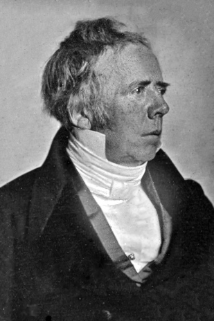
A Danish scientist named Hans Christian Oersted changed all that. He made the important discovery that electric current creates a magnetic field. But like many other important discoveries in science, Oersted’s discovery was just a lucky accident.
Oersted was presenting a demonstration to some science students. Ironically, he was trying to show them that electricity and magnetism are not related. He placed a wire with electric current flowing through it next to a compass, which has a magnetic needle. As he expected, the needle of the compass didn’t move. It just kept pointing toward Earth’s north magnetic pole.
So a curious student held the wire near the compass again, but in a different direction. To Oersted’s surprise, the needle of the compass swung toward the wire so it was no longer pointing north. Oersted was intrigued. He turned off the current in the wire to see what would happen to the compass needle. The needle swung back to its original position, pointing north once again. Oersted had discovered that an electric current creates a magnetic field. The magnetic field created by the current was strong enough to attract the needle of the nearby compass.
Oersted wanted to learn more about the magnetic field created by a current. He placed a compass at different locations around a wire with current flowing through it.

On our experiment the materials that we needed was:


/Faraday-58d1369b5f9b581d721fa176.jpg)
Just about a decade after Oersted discovered that electric current can produce a magnetic field, an English scientist named Michael Faraday discovered that the opposite is also true. A magnetic field can produce an electric current. This is known as Faraday’s law.

Faraday formulated that electromotive force produced around a closed path is proportional to the rate of change of the magnetic flux through any surface bounded by that path.
Faraday experimented by wrapping two insulated coils of wire around an iron ring. He found that, upon passing a current through one coil, a momentary current was induced in the other coil—mutual induction. If he moved a magnet through a loop of wire, an electric current flowed in that wire. The current also flowed if the loop was moved over a stationary magnet.


On our experiment the materials was:


The star-shaped lanterns are displayed hanging outside the house, along the busy streets of the cities and even in provincial towns and small villages. One of the most iconic symbol of Filipino Christmas spirit is the Christmas lantern or locally known as “parol”.

It is expected when December comes, Parol were already hang up to admire them and it is a symbols of Filipino Spirit. But before you gonna make a parol you mus plan your circuit diagram for the lights of the parol and by the help of Nehem our leader.
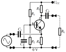
A circuit diagram (also known as an electrical diagram, elementary diagram, or electronic schematic) is a simplified conventional graphical representation of an electrical circuit.

A pictorial circuit diagram uses simple images of components, while a schematic diagram shows the components of the circuit as simplified standard symbols; both types show the connections between the devices, including power and signal connections. Arrangement of the components interconnections on the diagram does not correspond to their physical locations in the finished device

On a circuit diagram, the symbols for components are labelled with a descriptor or reference designator matching that on the list of parts. For example, C1 is the first capacitor, L1 is the first inductor, Q1 is the first transistor, and R1 is the first resistor (note that this is not written as a subscript, as in R1, L1,…).

Circuit is composed of individual electronic components, such as resistors, transistors, capacitors, inductors and diodes, connected by conductive wires or traces through which electric current can flow.
A parallel circuit is one that has two or more paths for the electricity to flow, the loads are parallel to each other. If the loads in this circuit were light bulbs and one blew out, there is still current flowing to the others because they are still in a direct path from the negative to positive terminals of the battery.  A Parallel circuit is one with several different paths for the electricity to travel. It’s like a river that has been divided up into smaller streams, however, all the streams come back to the same point to form the river once again.
It is a closed circuit in which the current follows one path, as opposed to a parallel circuit where the circuit is divided into two or more paths and it is called Series. In a series circuit, the current through each load is the same and the total voltage across the circuit is the sum of the voltages across each load. Unlike a parallel circuit, a series circuit will not function if one part is broken; that is, the current will not flow through the rest of the circuit.
In our Parol named Culture in Christmas, we used Parallel and Series because if the series will failed there will always be the parallel to support its other bulb.
A capacitor is a two-terminal, electrical component. Along with resistors and inductors, they are one of the most fundamental passive components we use. You would have to look very hard to find a circuit which didn’t have a capacitor in it.
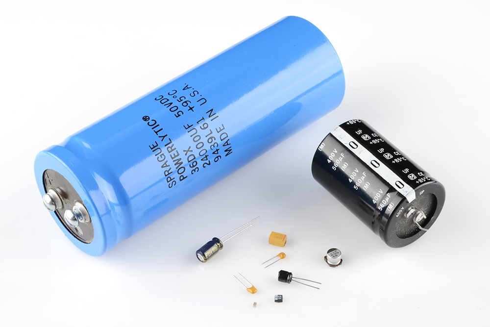
What makes capacitors special is their ability to store energy; they’re like a fully charged electric battery. Caps, as we usually refer to them, have all sorts of critical applications in circuits. Common applications include local energy storage, voltage spike suppression, and complex signal filtering.
The capacitance (C) of the capacitor is equal to the electric charge (Q) divided by the voltage (V):

C is the capacitance in farad (F)
Q is the electric charge in coulombs (C), that is stored on the capacitor
V is the voltage between the capacitor’s plates in volts (V)
Electric current is the flow of electric charge, which is what electrical components harness to light up, or spin, or do whatever they do. When current flows into a capacitor, the charges get “stuck” on the plates because they can’t get past the insulating dielectric. Electrons – negatively charged particles – are sucked into one of the plates, and it becomes overall negatively charged. The large mass of negative charges on one plate pushes away like charges on the other plate, making it positively charged.
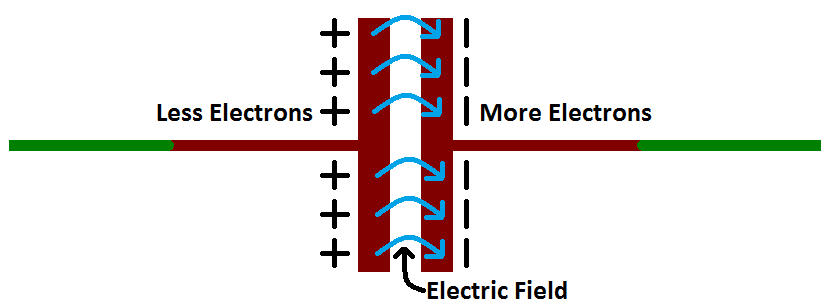
The positive and negative charges on each of these plates attract each other, because that’s what opposite charges do. But, with the dielectric sitting between them, as much as they want to come together, the charges will forever be stuck on the plate (until they have somewhere else to go). The stationary charges on these plates create an electric field, which influence electric potential energy and voltage. When charges group together on a capacitor like this, the cap is storing electric energy just as a battery might store chemical energy

With the help of capacitor on our circuit it is the energy storage of out diagram.
Resistors are electronic components which have a specific, never-changing electrical resistance. The resistor’s resistance limits the flow of electrons through a circuit.
They are passive components, meaning they only consume power (and can’t generate it). Resistors are usually added to circuits where they complement active components like op-amps, microcontrollers, and other integrated circuits. Commonly resistors are used to limit current, divide voltages, and pull-up I/O lines.

Schematic symbol
All resistors have two terminals, one connection on each end of the resistor. When modeled on a schematic, a resistor will show up as one of these two symbols:
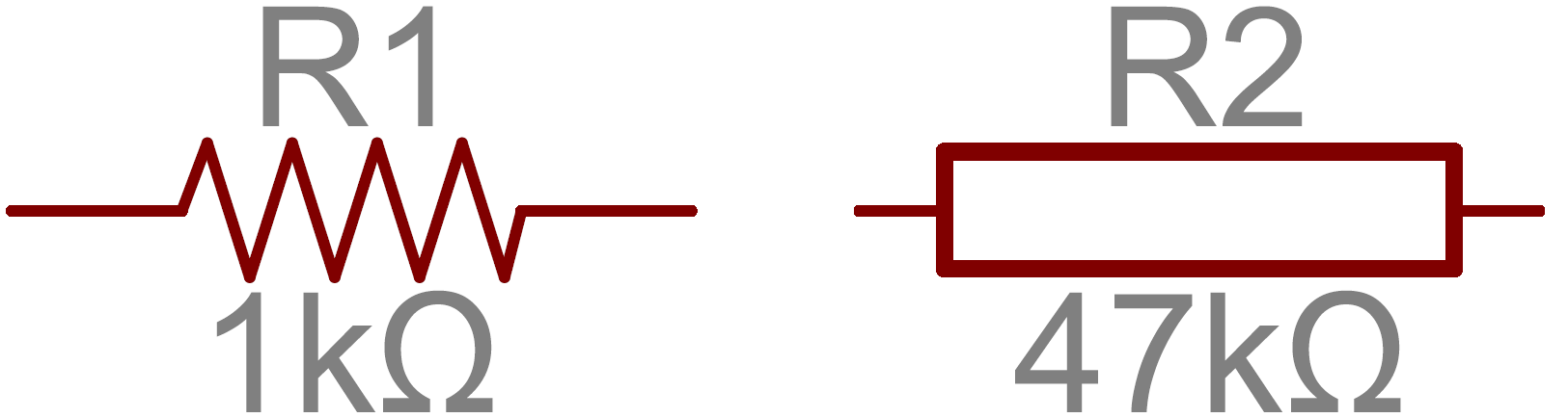
Two common resistor schematic symbols. R1 is an American-style 1kΩ resistor, and R2 is an international-style 47kΩ resistor.
The terminals of the resistor are each of the lines extending from the squiggle (or rectangle). Those are what connect to the rest of the circuit.
Transistors make our electronics world go ‘round. They’re critical as a control source in just about every modern circuit. Sometimes you see them, but more-often-than-not they’re hidden deep within the die of an integrated circuit. In this tutorial we’ll introduce you to the basics of the most common transistor around: the bi-polar junction transistor (BJT).
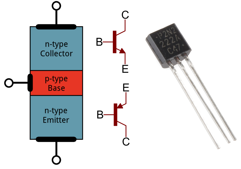 In small, discrete quantities, transistors can be used to create simple electronic switches, digital logic, and signal amplifying circuits. In quantities of thousands, millions, and even billions, transistors are interconnected and embedded into tiny chips to create computer memories, microprocessors, and other complex ICs.
Transistors are fundamentally three-terminal devices. On a bi-polar junction transistor (BJT), those pins are labeled collector (C), base (B), and emitter (E). The circuit symbols for both the NPN and PNP BJT are below:
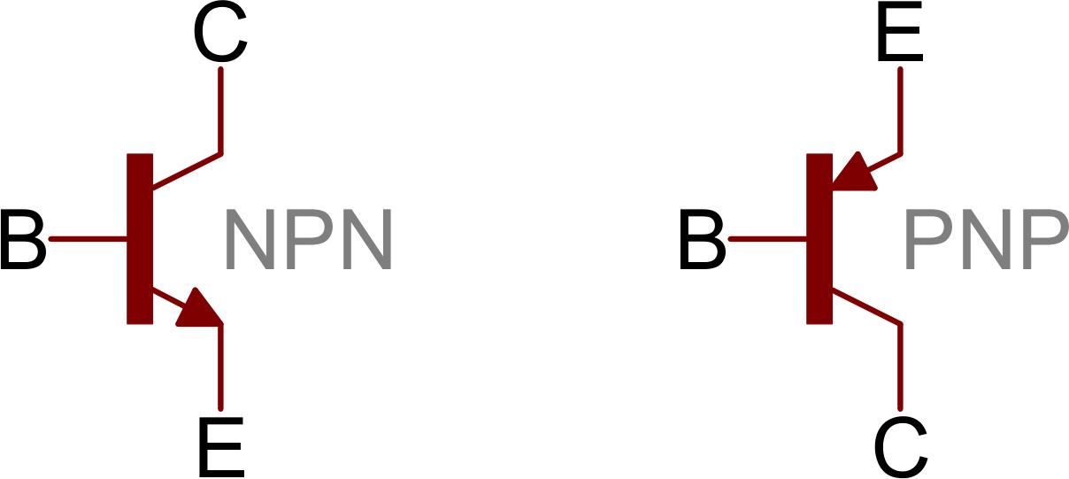
The only difference between an NPN and PNP is the direction of the arrow on the emitter. The arrow on an NPN points out, and on the PNP it points in.
Light emitting diodes, commonly called LEDs, are real unsung heroes in the electronics world. They do dozens of different jobs and are found in all kinds of devices. Among other things, they form numbers on digital clocks, transmit information from remote controls, light up watches and tell you when your appliances are turned on. Collected together, they can form images on a jumbo television screen or illuminate a traffic light.

A Light Emitting Diode (LED) consists of three layers: p-type semiconductor, n-type semiconductor and depletion layer. The p-type semiconductor and the n-type semiconductor are separated by a depletion region or depletion layer.
When trivalent impurities are added to the intrinsic or pure semiconductor, a p-type semiconductor is formed.
In p-type semiconductor, holes are the majority charge carriers and free electrons are the minority charge carriers. Thus, holes carry most of the electric current in p-type semiconductor.

When pentavalent impurities are added to the intrinsic semiconductor, an n-type semiconductor is formed.
In n-type semiconductor, free electrons are the majority charge carriers and holes are the minority charge carriers. Thus, free electrons carry most of the electric current in n-type semiconductor.

An electrical switch is any device used to interrupt the flow of electrons in a circuit. Switches are essentially binary devices: they are either completely on (“closed”) or completely off (“open”).
Types of switch:

Toggle switches are actuated by a lever angled in one of two or more positions. The common light switch used in household wiring is an example of a toggle switch. Most toggle switches will come to rest in any of their lever positions, while others have an internal spring mechanism returning the lever to a certain normal position, allowing for what is called “momentary” operation.
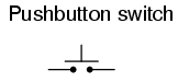
Pushbutton switches are two-position devices actuated with a button that is pressed and released. Most pushbutton switches have an internal spring mechanism returning the button to its “out,” or “unpressed,” position, for momentary operation. Some pushbutton switches will latch alternately on or off with every push of the button. Other pushbutton switches will stay in their “in,” or “pressed,” position until the button is pulled back out. This last type of pushbutton switches usually have a mushroom-shaped button for easy push-pull action.

Selector switches are actuated with a rotary knob or lever of some sort to select one of two or more positions. Like the toggle switch, selector switches can either rest in any of their positions or contain spring-return mechanisms for momentary operation.

A joystick switch is actuated by a lever free to move in more than one axis of motion. One or more of several switch contact mechanisms are actuated depending on which way the lever is pushed, and sometimes by how far it is pushed. The circle-and-dot notation on the switch symbol represents the direction of joystick lever motion required to actuate the contact. Joystick hand switches are commonly used for crane and robot control.
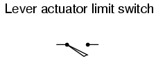
These limit switches closely resemble rugged toggle or selector hand switches fitted with a lever pushed by the machine part. Often, the levers are tipped with a small roller bearing, preventing the lever from being worn off by repeated contact with the machine part.
The Transformer can be thought of as an electrical component rather than an electronic component. A transformer basically is very simple static (or stationary) electro-magnetic passive electrical device that works on the principle of Faraday’s law of induction by converting electrical energy from one value to another.
The transformer does this by linking together two or more electrical circuits using a common oscillating magnetic circuit which is produced by the transformer itself. A transformer operates on the principals of “electromagnetic induction”, in the form of Mutual Induction.


In other words, for a transformer there is no direct electrical connection between the two coil windings, thereby giving it the name also of an Isolation Transformer. Generally, the primary winding of a transformer is connected to the input voltage supply and converts or transforms the electrical power into a magnetic field. While the job of the secondary winding is to convert this alternating magnetic field into electrical power producing the required output voltage as shown.

Notice that the two coil windings are not electrically connected but are only linked magnetically. A single-phase transformer can operate to either increase or decrease the voltage applied to the primary winding. When a transformer is used to “increase” the voltage on its secondary winding with respect to the primary, it is called a Step-up transformer. When it is used to “decrease” the voltage on the secondary winding with respect to the primary it is called a Step-down transformer.
However, a third condition exists in which a transformer produces the same voltage on its secondary as is applied to its primary winding. In other words, its output is identical with respect to voltage, current and power transferred. This type of transformer is called an “Impedance Transformer” and is mainly used for impedance matching or the isolation of adjoining electrical circuits.
Voltage is the pressure from an electrical circuit’s power source that pushes charged electrons (current) through a conducting loop, enabling them to do work such as illuminating a light.
Voltage is electric potential energy per unit charge, measured in joules per coulomb ( = volts). It is often referred to as “electric potential”, which then must be distinguished from electric potential energy by noting that the “potential” is a “per-unit-charge” quantity. Like mechanical potential energy, the zero of potential can be chosen at any point, so the difference in voltage is the quantity which is physically meaningful.

Power is the rate of energy consumption in an electrical circuit.
The electric power P is equal to the energy consumption E divided by the consumption time t:

P is the electric power in watt (W).
E is the energy consumption in joule (J).
t is the time in seconds (s).
The formulas are for single phase AC power.
For 3 phase AC power:
When line to line voltage (VL-L) is used in the formula, multiply the single phase power by square root of 3 (√3=1.73).
When line to zero voltage (VL-0) is used in the formula, multiply the single phase power by 3.
Real or true power is the power that is used to do the work on the load.
P is the real power in watts [W]
Vrms is the rms voltage = Vpeak/√2 in Volts [V]
Irms is the rms current = Ipeak/√2 in Amperes [A]
φ is the impedance phase angle = phase difference between voltage and current.
Reactive power is the power that is wasted and not used to do work on the load.
Q = Vrms Irms sin φ
Q is the reactive power in volt-ampere-reactive [VAR]
Vrms is the rms voltage = Vpeak/√2 in Volts [V]
Irms is the rms current = Ipeak/√2 in Amperes [A]
φ is the impedance phase angle = phase difference between voltage and current
Apparent power
The apparent power is the power that is supplied to the circuit.
S is the apparent power in Volt-amper [VA]
Vrms is the rms voltage = Vpeak/√2 in Volts [V]
Irms is the rms current = Ipeak/√2 in Amperes [A]
Real / reactive / apparent powers relatio
The real power P and reactive power Q give together the apparent power S:
P is the real power in watts [W]
Q is the reactive power in volt-ampere-reactive [VAR]
S is the apparent power in Volt-amper [VA]
Electric Consumption is the rate, per unit time, at which electrical energy is transferred by an electric circuit. The SI unit of power is the watt, one joule per second.
Electric power is usually produced by electric generators, but can also be supplied by sources such as electric batteries. It is usually supplied to businesses and homes by the electric power industry through an electric power grid. Electric power is usually sold by the kilowatt hour (3.6 MJ) which is the product of power in kilowatts multiplied by running time in hours. Electric utilities measure power using an electricity meter, which keeps a running total of the electric energy delivered to a customer.
Electrical power provides a low entropy form of energy and can be carried long distances and converted into other forms of energy such as motion, light or heat with high energy efficiency
Electric power, like mechanical power, is the rate of doing work, measured in watts, and represented by the letter P. The term wattage is used colloquially to mean “electric power in watts.” The electric power in watts produced by an electric current I consisting of a charge of Q coulombs every t seconds passing through an electric potential (voltage) difference of V is:
where
My experience in doing this parol is to built some friendship with my Pusi Fam (groupmates) because in all sleepless night we have at we finished our “parol” it is really worth it. That we must not forget the culture we have because it will always be here with us. I also learn how to be an electrician I guess? hahahaha because of those wirings or in short the circuit diagram. At first it is really hard to plan and also doing it because sometimes the bulb might explode. But all of those sleepless night, pain, and tiredness it is really worth it. Kapag binigay mo talaga ang lahat ng effort mo minsan nagiging worth it naman. to my groupmates they are not only my classmate or friends but they are my fam now.


“On graduating from the school, a studious young man who would withstand the tedium and monotomy of his duties has no choice but to lose himself in some branch of science or literature completely irrelevant to his assignment. ” – Charles-Augustin de Coulomb

Formula of Coulomb’s Law

The Coulomb’s law equation provides an accurate description of the force between two objects whenever the objects act as point charges. A charged conducting sphere interacts with other charged objects as though all of its charge were located at its center. While the charge is uniformly spread across the surface of the sphere, the center of charge can be considered to be the center of the sphere. The sphere acts as a point charge with its excess charge located at its center.
Electrons should fall into the nucleus even if they weren’t attracted by the charge of the proton, but for me the electrons is moving really fast around the nucleus and because of the electrons have a low mass, even a small amount of energy makes it move very fast. And as i can remember the answer of sir lex of this question that if one takes a positive nucleus and a stationary negative electron, everybody knows that the nucleus will attract the electron, electron will start moving towards the nucleus until the electron falls to the nucleus. But in reality this will going to happen.


“nothing in life is certain except death, taxes, and the second law of thermodynamics” – Seth Lloyd
the Second Law of Thermodynamics s a general principle which places constraints upon the direction of heat transfer and the attainable efficiency of heat engines. in first law of thermodynamics wherein, energy is never created or destroyed, that means that energy can just be recycled over and over again.
well…. energy cannot be created or destroyed, but it can change from more-useful forms into less-useful forms. As it turns out, in every real-world energy transfer or transformation, some amount of energy is converted.
ENTROPY – a degree of randomness or disorder in a system
wherein, the First Law of Thermodynamics tells us about conservation of energy among processes, while the Second Law of Thermodynamics talks about the directional of the processes, that is, from lower to higher entropy.
In learning this second law of thermodynamics my experienced in learning this topic at first it is really hard but at the end of the day i can say that if its really hard to understand don’t rush yourself because in learning a certain thing you can learn by step by step. uhmmm our teacher gave us an activity wherein you’ll find a partner to answer the worksheet so again me and my partner debate because we don’t have the same answer on solving the question so we need some explanation from the other groups. we share our knowledge to each other but our teacher sir lex gave us more knowledge about the topic.
In our daily life not in all times you can stand by your own but you need somebody so that he/she can correct the wrong that you have done. A person who will guide you at the end of the day that teach you and to understand the things that you don’t know.
In learning the second law of thermodynamics: heat engines, it is impossible to extract an amount of heat QH from a hot reservoir and use it all to do work W . Some amount of heat QC must be exhausted to a cold reservoir.

This is sometimes called the “first form” of the second law, and is referred to as the Kelvin-Planck statement of the second law.
KELVIN-PLANCK t is impossible to devise a cyclically operating device, the sole effect of which is to absorb energy in the form of heat from a single thermal reservoir and to deliver an equivalent amount of work. This implies that it is impossible to build a heat engine that has 100% thermal efficiency.


“In this house, we obey the laws of thermodynamics” – Seth Llloyd. It is a branch of physics concerned with heat and temperature and their relation to energy and work. The behavior of these quantities is governed by the four laws of thermodynamics, irrespective of the composition or specific properties of the material or system in question.
THERMODYNAMICS
is a branch of physics concerned with heat and temperature and their relation to energy and work.
In this First Law of Thermodynamics we answered the given activities to us that where in, in that activity we learned more about the lesson.


with the helped of this activity I learned more about the first law of thermodynamics. At first it is really hard for me but because this activity is grouped by two people we used to helped each other.
I learned that if the temperature T of the gas increases, the gas molecules speed up and the internal energy U of the gas increases -which means ΔU, is positive while if the temperature T of the gas decreases, the gas molecules slow down, and the internal energy U of the gas decreases -which means ΔU, is negative.
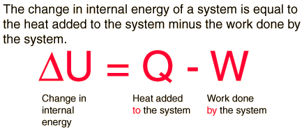
It is typical for chemistry texts to write the first law as ΔU=Q+W. It is the same law, of course – the thermodynamic expression of the conservation of energy principle. It is just that W is defined as the work done on the system instead of work done by the system. In the context of physics, the common scenario is one of adding heat to a volume of gas and using the expansion of that gas to do work, as in the pushing down of a piston in an internal combustion engine.
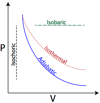
A system can be described by three thermodynamic variables — pressure, volume, and temperature. Well, maybe it’s only two variables. With everything tied together by the ideal gas law, one variable can always be described as dependent on the other two.
Temperature is the slave of pressure and volume on a pressure-volume digram (PV diagram).
The best part of this activity was when me and my partner (my enemy, in answering the activity) we always have a debate because sometimes we don’t have the same answer but at the end with the knowledge we have we need to explain our own explanation to each other. We always helped each other in order to have a correct answer. If you really helped one another you’ll have a better outcome.
The activities that was given it is really a thumbs up for me, because the students will learned more in the activities that was given. They need to answer the following question to have some points and also if there was a wrong answer they can talk to each other so that they can help one another. Because not all of them have the same knowledge.
In our life there will always be one person who will correct your mistake. A person that can share his/her knowledge.and with that team building/cooperation you have on one another at the end it will really be WORTH IT.



